Sequencer
The Sequencer section allows you to configure four sequencer parts that run in parallel and produce musical events. Each part can generate notes and modulation values based on its current state and the parameters you set.
To access the Sequencer, you need to open the floating plug-in window, a separate window that shows the extended graphical interface of the plug-in. You can open it by clicking on the Plug-In Window button (  ) located at the bottom left corner of the Flow's rack view.
Part Selector
The Part Selector lets you choose one of the four sequencer parts to edit. Each part has a separate state machine with its own settings and parameters that you can customize, such as the number of states, the transition probabilities, the notes and modulation values that state machine generates, and other options.

To select a sequencer part to edit, you can click on one of the four buttons labeled P1, P2, P3, and P4.
States Hierarchy
Each sequencer part consists of different types of states that store musical information or rules.
There are two types of states: Triggers and State Machines.
- A Trigger is a basic state that outputs a note or a modulation value when it is activated;
- A State Machine is an advanced state that contains other states inside it. These states can be either Triggers or nested State Machines.
This creates a hierarchical structure of states within states, where each state can have different settings and parameters:
The highest level of the hierarchy, also called the root state, is always a State Machine. The lowest level is always a Trigger. The hierarchy can have up to 8 levels of nested states, allowing you to create a complex models that control the behavior of your musical patterns.
State Machines and Triggers: Common Features
Both state types, State Machine and Trigger, have some parameters and controls that are common to them.
These common controls include:
State Type
This option allows you to switch between State Machine and Trigger state types.

The root of the hierarchy is always a State Machine and its type cannot be changed.
Wrap Command
The Wrap button is a useful feature that lets you create more complex musical structures from simpler ones. It works by creating a new container state machine that has the wrapped state as its first sub-state.

After wrapping a state, you can then add more sub-states to the container state machine and configure their transitions and parameters. This way, you can reuse existing states as building blocks for higher-level musical models.
- Wrap: Before
- Wrap: After
Wrapping allows you to grow your musical ideas in an outward direction, adding more variety and richness to your compositions. For example, you can wrap a sequence of notes into an arpeggio on State 1, and then create another arpeggio on State 2 with different notes or settings. Or you can wrap a chord progression into a section A of your song and then add a section B with a different chord progression.
The Wrap button is only enabled when the resulting hierarchy depth after wrapping does not exceed the maximum of 8 levels.
State Playback Indicator
Each state has a Playback Indicator in the top right corner. This indicator shows the playback status of the state.

If the indicator is lit, it means the state is playing. If the indicator is gray, it means the state is paused or stopped.
State Execution Indicators
State Execution Indicators are visual cues that show the status of each state in a State Machine or a Trigger. They are shaped like triangles and located on the left side of the state. They help you track the execution flow and the playback of your states.
- For a State Machine, the indicator points to the state that is currently running. Only one state can be active at a time in a State Machine.
- For a Trigger, the indicators point to the notes or modulation values that are currently playing. Multiple indicators can be active simultaneously in a Trigger.
The color of the indicator reflects the activity of the state:
- A white triangle means that the state is active and producing notes or modulation values.
- A gray triangle means that the state is inactive and not playing. It is shown for reference.
You can use the State Execution Indicators to monitor the behavior of your State Machines and Triggers. They can help you fine-tune your state transition logic and adjust trigger configurations.
State Machine
State Machine lets you describe the behavior of a musical system in terms of states and transitions between them.
States Number
The States Number parameter specifies how many states are in the state machine.
- Range: 2 – 8
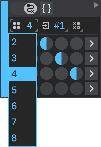
If you need more than eight states, you can use high-level states, which are states that contain other state machines inside them. High-level states allow you to create sequences of arbitrary length and complexity.
State Selector
The State Selector lets you see and switch between different states of a state machine.

A state can be a plain Trigger state, or a nested State Machine, which will in turn have its own nested sub-states.
Initial State
The Initial State is the state that the state machine begins with when it is activated.
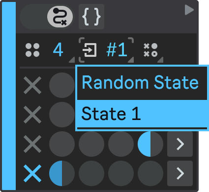
You can choose one of two options for the Initial State:
- Random State: The state machine will pick a random state from its set of states every time it starts;
- State 1: The state machine will always start from the first state in its set of states.
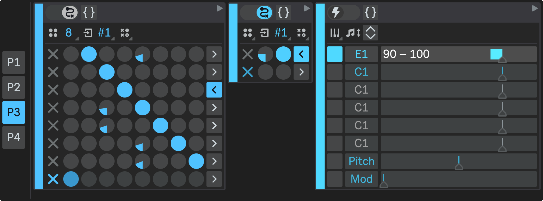
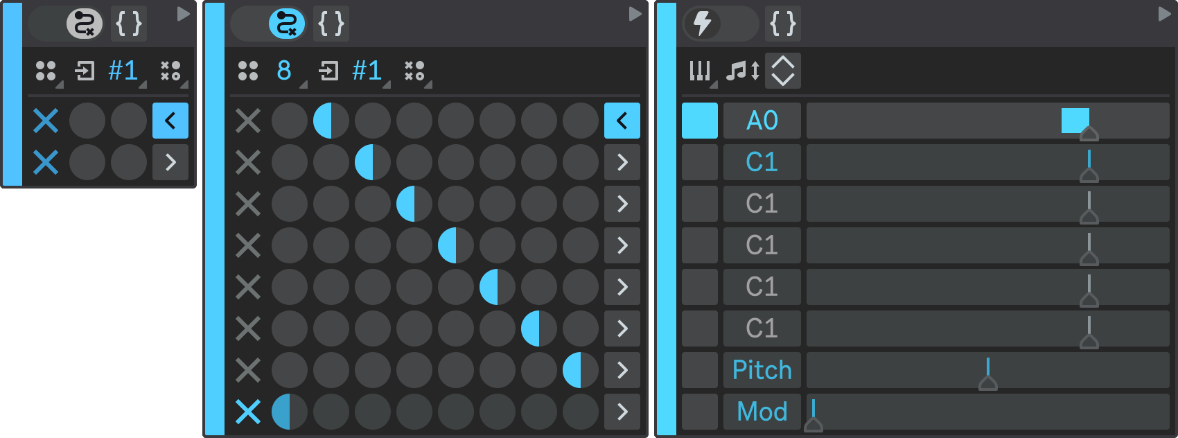
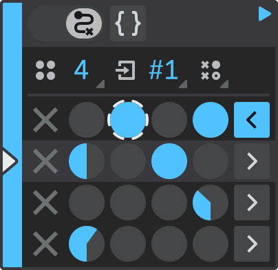
State Transition Matrix
A State Transition Matrix is a table that shows how a state machine moves, or transitions, from one state to another. Each row and column represent a state, and each cell represents a transition from the row state to the column state.
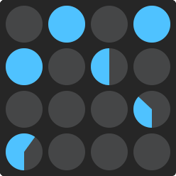
The larger the cell value relative to other cell values in the same row, the higher the chance that the state machine will choose that transition over the others:
- If there are two transitions with the same value dialed, the chance is always 50/50, no matter what is the exact value dialed in both cells;
- If there are two transitions, one with the cell fully dialed, and another dialed half-way, the chance of picking the first one is twice as high as picking the second one;
- If there is only one possible transition, its exact value doesn't matter because probabilities of other transitions are zero.
- Hold down Shift while dragging to adjust the cell value more precisely.
- Double-click a cell to dial it half-way. Double-click again to reset its value to zero.
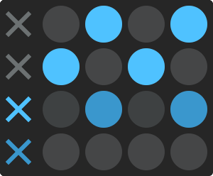
Final States
To the left of the State Transition Matrix, there is a column of checkboxes that determine the Final States of the state machine. A final state is a state that makes the state machine exit when it is reached. If a state is marked as final, any state transitions defined in the State Transition Matrix for it are ignored and the corresponding matrix row is dimmed in the user interface.
A state machine can have zero, one or more final states, depending on its purpose and design. When a state machine reaches a final state, different things can happen depending on its level in the hierarchy:
- If the state machine is nested inside another state machine, it means that it has completed its execution and gives the control back to its parent state machine. The parent state machine then resumes its execution from where it left off.
- If the state machine is the root state machine (the highest level in the hierarchy), it means that the whole state machine has finished its execution. There is no higher level to return to, so the state machine restarts from its Initial State.
If the state machine has a state that does not have any outgoing transitions, it is also considered a final state. This is shown in the UI by automatically highlighting the final state checkbox for that state.
If a state machine does not have any final states, it will keep running indefinitely, unless you manually restart the playback, or unless the Reset Interval is reached. The Reset Interval is a time limit that you can set for each sequencer part in the Mixer section to make it reset automatically after a certain period of time.
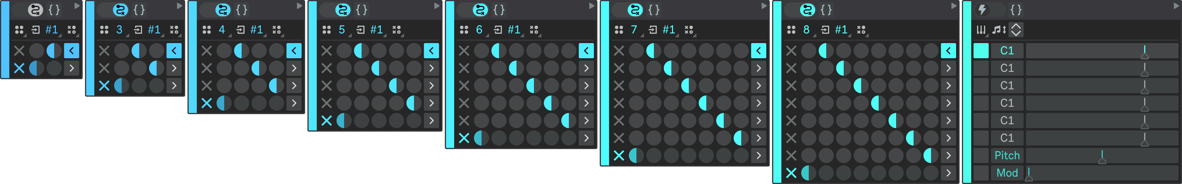
Pattern Selector
The Pattern Selector allows you to fill in the State Transition Matrix and the Final States array with one of the pre-defined algorithms. These algorithms are:
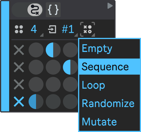
- Empty: This algorithm clears both the State Transition Matrix and the Final States array, leaving them blank.
- Sequence: This algorithm sets up the state machine so that it executes its states in a sequential order, starting from the first state and ending at the last state. It also marks the last state as final in the Final States array, which means that the state machine will exit when it reaches that state.
- Loop: This algorithm is similar to Sequence, but it does not mark the last state as final. Instead, it creates a loop that connects the last state back to the first state, so that the state machine will keep cycling through its states without exiting.
- Randomize: This algorithm fills in the State Transition Matrix with random values, creating a state machine that transitions between states unpredictably. It does not affect the Final States array, so you can manually mark any state as final if you want.
- Mutate: This algorithm modifies the State Transition Matrix by adding or subtracting a small random value to each cell. This creates a slight variation of the original state machine, which can be useful for experimentation. It does not affect the Final States array either.
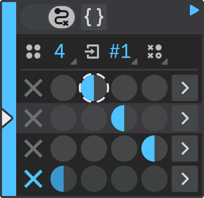
State Transition Indicator
The State Transition Indicator is a visual feature that shows the last selected transition in a State Transition Matrix and helps you to track the state machine's execution flow. It uses a dashed circle around the selected transition.

The color of the circle indicates the status of the state: white means that the state is currently active, while gray means that the state has finished its execution, and is displayed for reference.
Active State Row Indicator
The Active State Row Indicator highlights the state which is currently being executed and helps you to monitor the behavior of your state machine in real time.
The color of the row highlight indicates the status of the state: lighter color means that the state is currently active, while dimmed means that the state has finished its execution, and is displayed for reference.
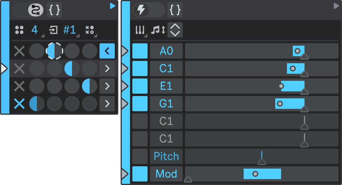
Trigger
A Trigger state lets you define MIDI notes and modulation values that will be played when the trigger is activated.
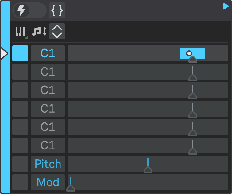
Note Triggers
A Trigger state has 6 Note Triggers that define the pitch and velocity range of each note.

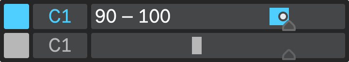
Note Trigger Activator
The Note Trigger Activator checkbox determines whether a note trigger is active or not. If it is unchecked, the note trigger will not produce any output. You can use this option to enable or disable a note trigger without changing its settings.
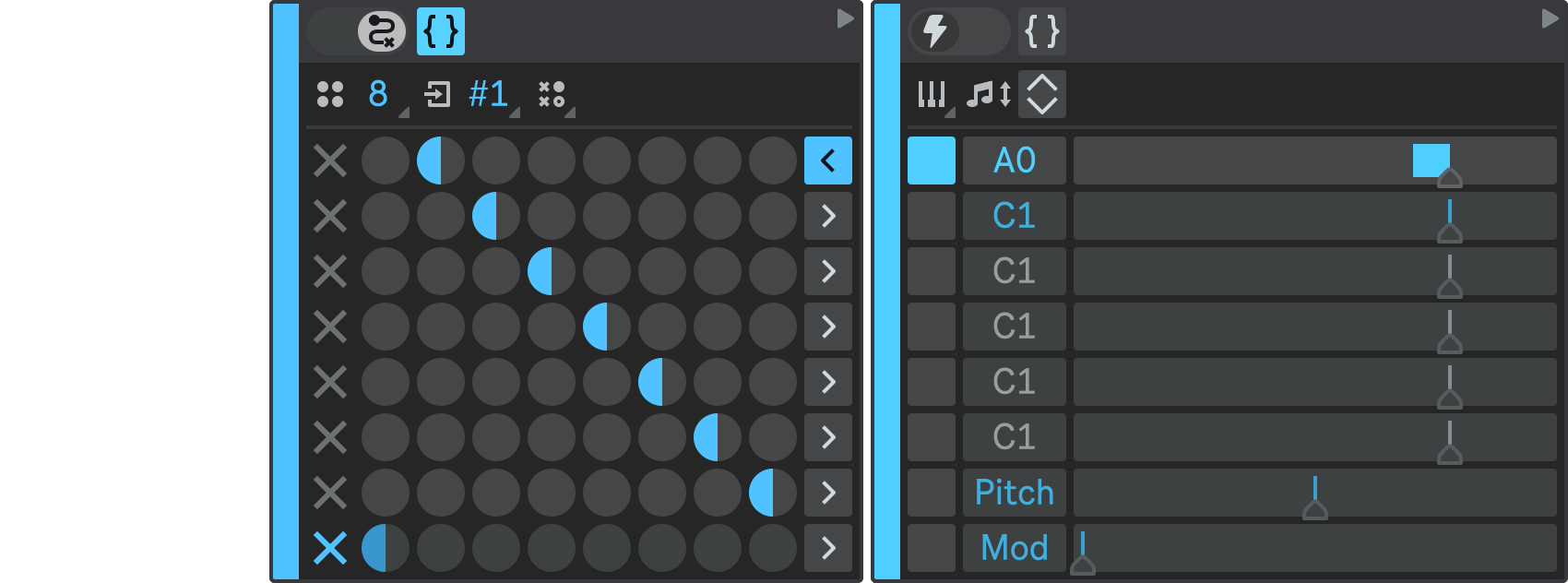
Pitch
The Pitch parameter controls the musical tone of the note that the trigger will play.
- Default value: C1.
When you change the pitch, the Note Trigger Activator turns on automatically (unless you choose the default pitch), so that the note trigger is ready to play the note when you start the playback.
- Type in the pitch value directly from the keyboard.
- Use the Up and Down keys on your keyboard to adjust the pitch by one semitone.
- Use the Shift + Up / Down keys on your keyboard to adjust the pitch by one octave.
- Double-click the Pitch to reset it to its default value of C1.
If the Note Preview option is enabled in the device configuration, the note will be played every time you change its pitch. This is useful when you are working with sliced samples or drum kits, as it lets you audition the sound of each note. The Note Preview only works when Ableton Live playback is stopped, so it won't interfere with your tracks.
If there are multiple note triggers with the same pitch configured, only the first one will be used. The rest of the notes with the same pitch will be ignored, and they will appear grayed out on the user interface.
When multiple sequencer parts are running in parallel, they may produce the same note at the same time. This can cause unwanted overlap and interference.
To prevent this, each sequencer part has a priority level, from P1 (highest) to P4 (lowest). The priority level determines which note will be played when there is a conflict. The part with higher priority has precedence and can output its note, while the part with lower priority has to suppress its note. This way, the sequencer parts can run in parallel without clashing.
Velocity Range Slider
The Velocity range slider determines the range of MIDI velocity values that can be produced by the note trigger. The velocity value will be randomly chosen from this range when the note trigger is activated.
Underneath the range slider, there is a small triangular Reset Button that resets the velocity range to the default.
- Range: 0 – 127;
- Default value: 100.
When you change the velocity range, the Note Trigger Activator turns on automatically (unless you choose the default velocity).
- Hold down Shift while dragging to adjust the range slider value more precisely.
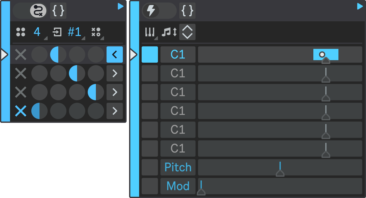
Generated Velocity Indicator
When a note trigger produces output, the generated velocity value will be indicated on the velocity range slider (  ). A white color indicates that the note trigger is currently playing; a gray color indicates that the note trigger has finished playing and shows the last generated velocity value for reference.
Pitch Bend and Modulation Wheel Triggers
In addition to the Note Triggers, there are also Pitch Bend and Mod Wheel triggers that define the pitch bend and modulation wheel values produced when the Trigger is activated.
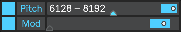
Modulation Trigger Activator
The Modulation Trigger Activator checkbox determines whether a corresponding modulation trigger is active or not. If it is unchecked, the modulation trigger will not produce any output. You can use this option to enable or disable a note trigger without changing its settings.
Value Range Slider
The Modulation Value range slider determines the range of modulation MIDI values that can be produced by the modulation trigger. The modulation value will be randomly chosen from this range when the modulation trigger is executed.
Underneath the value slider, there is a small triangular Reset Button that resets the velocity range to the default.
- Ranges:
- Pitch Bend: -8191 – 8192;
- Mod Wheel: 0 – 127.
- Default values:
- Pitch Bend: 0;
- Mod Wheel: 0.
When you change the modulation value range, the corresponding Modulation Trigger Activator turns on automatically (unless you choose the default value).
- Hold down Shift while dragging to adjust the range slider value more precisely.
Generated Value Indicator
When a modulation trigger produces output, the generated value will be indicated on the value range slider ( ). A white color indicates that the modulation trigger is currently playing; a gray color indicates that the modulation trigger has finished playing and shows the last generated value for reference.
Chord Selector
The Chord Selector lets you create different chords by filling the note triggers with predefined chord types. You can also reset the note triggers to their default values by choosing Empty option.
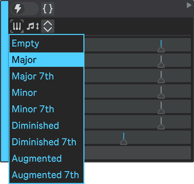
To use the Chord Selector, first choose the root note of the chord you want to create by setting the pitch of the first Note Trigger. Then, select one of the available chord types from the dropdown menu.
For example, if you want to create an A minor chord, set the first note trigger to A and select Minor from the menu. The velocity ranges of the note triggers will also be reset to their default values.
If Note Preview is enabled, you will hear how the chord sounds when you select it. This way, you can easily experiment with different chords and harmonies.
Pitch Shift
The Pitch Shift buttons are useful for changing the pitch of all the enabled note triggers at once.

- Hold down Shift while clicking up or down button to shift by one octave instead of one semitone.
If Note Preview is enabled, you will hear how the notes sounds when you shift their pitches.